



On a long-endurance UAV, every component competes for the same two things: mass and volume. The fuel system is usually one of the worst offenders on both counts and one of the least examined.
A rigid tank has to be in a shape that can be manufactured, which is rarely the shape of the cavity it sits in. The result is dead space in the wing root, dead space around the spar, and a structure carrying more tank than fuel.
Flexible reinforced urethane bladders resolve this in a different way. Instead of building a vessel and fitting the airframe around it, the bladder takes on the shape of whatever volume is already there.
Table of Contents
The Material: Coated Fabric, Not Film
A fuel bladder is a composite, with two halves doing different jobs.
The barrier layer is typically a fuel-grade thermoplastic polyurethane (TPU), though it isn’t the only chemistry in use. Nitrile (Buna-N) compounds and fluor elastomer-coated fabrics also see service as barrier layers, particularly where fuel chemistry pushes TPU’s limits. TPU’s value is low permeability. It holds hydrocarbon fuel and JP10 without significant vapor transmission through the wall. And it has a weight advantage over elastomer-based alternatives. That vapor control matters more in a UAV than in a ground vehicle, because fuel vapor migrating into a sealed avionics bay is both a corrosion problem and an ignition problem. The tradeoff is that some fuel blends, particularly those with high aromatic content or oxygenate additives, can swell or extract plasticizer from polyurethane over long-term exposure, which is why barrier chemistry has to be qualified.
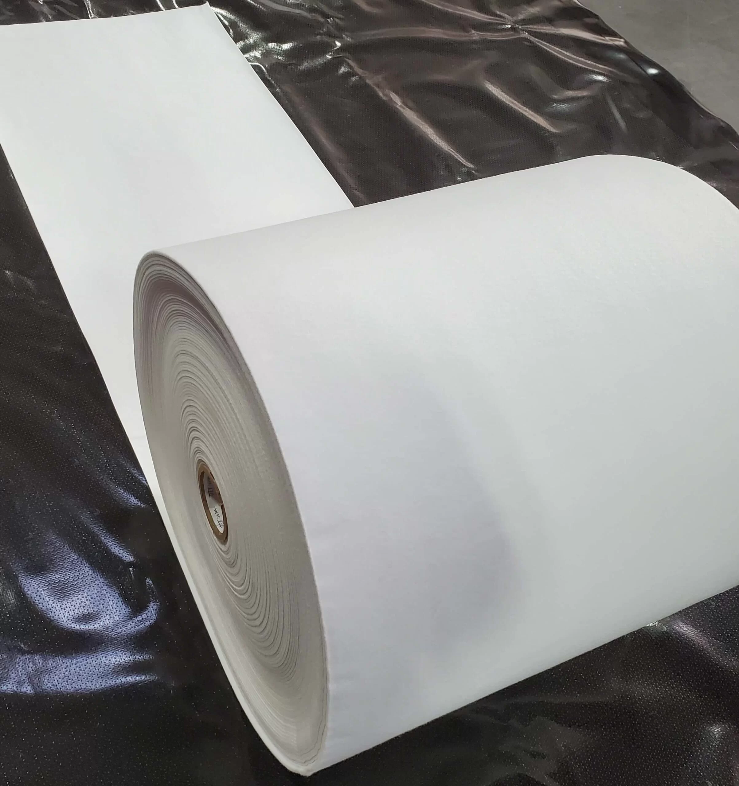
The reinforcement layer is a woven technical textile, typically a high-tenacity polyester or nylon base cloth. Unreinforced polyurethane will stretch under hydrostatic head and cyclic loading. The woven substrate carries tensile load, so the bladder holds dimensional stability when full, while the coating handles containment. The fabric is encapsulated in the coating so the weave is never in direct contact with fuel. Films are more suited for unique cavities so they can be pressurized into the cramped spaces when filled with fuel.
Seams and port attachments are made by RF welding or thermal bonding rather than adhesive, producing a fused joint with parent-material strength instead of a bond line that can be attacked by fuel.
Why Flexible Wins on a UAV Airframe
Volumetric efficiency. A conformable bladder fills irregular, non-linear cavities that a rigid tank cannot. On airframes where fuel volume directly sets endurance, recovering otherwise unusable space in wing bays and fuselage sections is one of the cheapest ways available to increase range. No aerodynamic or structural redesign is required.
Mass reduction. A coated fabric bladder weighs a fraction of an equivalent aluminum or composite vessel. On an aircraft where payload and fuel trade against each other directly, that weight reduction comes back as capability.
Slosh control. Rigid tanks develop a large ullage space as fuel burns off, and the resulting free-surface movement shifts the center of gravity during maneuvers. A flexible bladder collapses as it empties, so the air pocket never forms. Where additional control is needed, internal baffles can be RF-welded into the bladder to dampen fluid inertia. Some designs incorporate reticulated foam inside cells for combined slosh dampening and explosion suppression, the same approach used in crash-resistant rotorcraft fuel cells.
Impact behavior. This is the argument that usually closes the discussion. A rigid tank under hard impact fails by fracture, and a fractured fuel tank is a fire. A reinforced flexible bladder deforms and absorbs energy instead. The crash-resistant fuel cell field in rotorcraft as governed in the U.S. by specifications such as MIL-DTL-27422 is built on this principle, The physics carry over directly to UAV recovery events and hard landings.
Operating Environment
UAV flight profiles are demanding in ways that eliminate a lot of candidate materials:
Thermal range. Coated fabrics for this service need to stay flexible through a wide low-to-high temperature band. Brittleness at altitude-soak temperatures is a failure mode, not an inconvenience.
Altitude and pressure cycling. Repeated pressure differential across the bladder wall over many sorties is a fatigue condition and one reason welded seams are preferred over bonded ones.
Fuel chemistry. Different fuels attack polymers differently, and compatibility has to be established against the specific fuel, not against “hydrocarbons” as a category. This has gotten more important as UAV programs move toward heavy-fuel engines running on JP-8 or Jet-A, consistent with DoD single-fuel-forward policy. Those fuels have different aromatic content and additive packages than the gasoline blends earlier small-UAV engines were designed around, and a barrier qualified for one is not automatically qualified for the other.
Electrostatic discharge. Fuel moving through a bladder during fill, flight, and slosh generates static charge, and a flexible coated-fabric cell doesn’t dissipate it the way a metal tank does. Fuel bladder systems typically require a conductive path via either a conductive layer or thread woven into the fabric or a bonding strap at the fill and vent ports. These ground the system to the airframe and prevent static buildup near a fuel-vapor environment.
Hardware Integration
A bladder is only as good as its connections. Fittings, access hatches, fuel pickups, vents, and quantity-sensor pass-throughs are integrated into the membrane during fabrication. Anodized aluminum or stainless ports are fused into the coated fabric so there’s no mechanical clamp relying on gasket compression to stay sealed through thermal and pressure cycling. These ports also serve as the electrical bonding point back to the airframe structure, so grounding continuity should be verified as part of installation, not assumed from the fitting alone.
Venting is part of this same design problem. As fuel burns off and the bladder collapses, or as it heats and expands, the cell needs a controlled path to equalize pressure without admitting contamination or allowing fuel siphoning at extreme attitudes. Vent routing and sizing are as much a design-stage decision as pickup placement.
Port placement generally is a design-stage decision, not a late one. Pickup location determines usable versus residual fuel at attitude, and it’s the item most often revisited after first flight.
What to Specify
When you’re evaluating coated fabric for a fuel containment application, the questions that actually drive material selection are:
- Which fuel, specifically, and is there a compatibility test report against that fuel and that coating?
- Volume and cavity geometry — envelope drawings beat nominal capacity
- Load and maneuver profile — maximum G, pressure cycles, expected service life in sorties
- Qualification requirements — which military or airworthiness specification the finished cell has to meet (MIL-DTL-27422 is the common baseline reference for crash-resistant construction)
- Whether self-sealing construction is required. This adds one or more internal layers of uncured natural or synthetic rubber that swell on contact with fuel to plug small-arms or fragment punctures. It changes the layup, weight, and thickness substantially, so it needs to be decided earlier rather than added later
- Electrical bonding requirements for static dissipation and grounding continuity
- Temperature and altitude envelope
Work With Us on Material Selection
E Squared Tech Textiles supplies engineered coated fabrics for demanding containment and inflatable structure applications. When you’re developing a fuel containment system and need to evaluate substrate weight, coating chemistry, and weld performance against your operating envelope, our team will work from your requirements rather than a general catalog.